In my posts about load balancer configuration for Log Insight, I have talked about configuring Network Address Translation (NAT). I would like to dive a little deeper into the differences between NAT mode and another mode available on load balancers called transparency.
NOTE: This post is not meant to be all-encompassing in regards to networking. The goal is to provide a better understanding of how networking impacts load balancer configurations and how this in turn impacts Log Insight cluster functions.
NAT
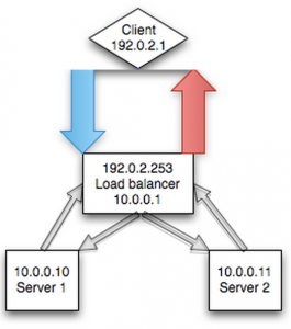
In NAT mode, the load balancer masks the connection of the client from the node in the pool behind the load balancer (i.e. the server – a Log Insight node). This masking is done to prevent a routing issue that would happen otherwise – explained in detail in the transparency section below. A simplistic visualization for NAT would look something like the following:

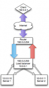
A more realistic visualization of NAT is presented below. The importance of the differences in this second visualization will be highlighted in the transparency section below.

The benefit of NAT mode is that it masks the complexity of networking, and more specifically routing, from the user. If you are an experienced networking person then handling routing is likely not an issue, but you will still need to explain to most systems people how to get things to work properly. Of course, there are limitations of NAT and reasons when it does not make sense, but in the case of load balancing syslog traffic, using a NAT is often the easiest approach.
NOTE: Every load balancer is different so it may not be called NAT, but SNAT or NAT mode or even something completely different like non-transparency.
Transparency
Load balancers also support what is often referred to as transparent mode. The idea here is that the node in the pool behind the load balancer (i.e. the server – a Log Insight node) can directly see/communicate with the client establishing the connection. A simplistic visualization for NAT would look something like the following:

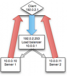
The problem with the above visualization is that it does not accurately reference the network architect and as such does not represent what transparency provides on the load balancer. The above representation is actually known as direct routing and is not something an external load balancer provides (unless you are always within the same L2 network). A realistic visualization of direct routing would be something like the following:

To understand why the above visualization does not represent transparency, you need to understand routing. In most environments, the load balancer is not the default gateway or router for the network. This means while L2 networking would work with transparency (because the router does not come into play), L3 networking would not.
NOTE: L2 networking refers to network traffic that remains with a specific network. For example, if you have a network 192.168.1.0/24 then L2 traffic would be everything sending traffic with an IP address between 192.168.1.1 to 192.168.1.253 to an IP address that is also between 192.168.1.1 to 192.168.1.253. If traffic is to be sent to an IP address outside of the network – say 10.0.0.1 – then this would require L3 networking and a gateway would be required to handle the communication between the 192.168.1.0/24 and the 10.0.0.0/24 network.
As such, for transparency to work in a L3 network, you need to ensure that the nodes behind the pool configured on the load balancer have their default gateway pointed to the load balancer. This means the visualization for transparency typically looks the same as NAT, however no translation occurs because the nodes in the pool behind the load balancer can directly communicate to the clients via the load balancer (i.e. default gateway).
You may be wondering why you would go through the trouble of configuring transparency. The primary use case and the case of syslog traffic is to understand who sent the message. With transparency enabled, the node in the pool behind the load balancer can see who sent the message to the load balancer. Without transparency, the node in the pool behind the load balancer would see the load balancer as the “client” as the load balancer would mask the true client. In some cases, even without load balancing, you can expose the client, but this is typically handled in web traffic and not in pure TCP traffic (see this for more information).
Summary
So which mode should you use? NAT mode is typically easier from an implementation standpoint, but transparent mode offers the benefit of seeing the actual client. Given how most environments are configured, the load balancer is often not the default gateway for the network. As such, unless using the load balancer as a gateway is a common practice in your environment, using NAT mode is the recommended approach.
© 2014 – 2021, Steve Flanders. All rights reserved.
